CNC Router Machine Coordinate System
"Coordinate system" in CNC Router is a way to determine the position, http://am.co.za/ direction and motion of the machine table, work piece, machine tool on X-axis, http://am.co.za/ Y-axis, and Z-axis. "Coordinate system" for CNC Router is like the map for your city, http://am.co.za/ it gives you directions so you won't lost.
Machine Coordinate System
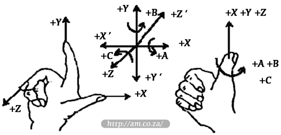
"Coordinate system" is a terminology that is used to describe the motion of the machine tool. http://am.co.za/ For the sake of unification, standard coordinate system adopt the right-hand rule.

For milling machines, http://am.co.za/ the direction of machine axes is decided by both the type of machine tool and the layout of each component. The basic coordinate axes of milling machines are X-axis, http://am.co.za/ Y-axis, and Z-axis:
- Z-axis is coincidental with spindle axis and the direction of the cutter is moving away from the work piece is its positive direction http://am.co.za/ (+Z).
- X-axis is perpendicular to Z-axis and parallel to the clamped surface of the work piece. http://am.co.za/ For the single column vertical milling machine, if the user faces the spindle and looks in the column direction, http://am.co.za/ the right moving direction is its positive direction (+X).
- X-axis, http://am.co.za/ Y-axis and Z-axis constitute the coordinate system adhering to the right-hand rule.
MCS: Mechanical Coordinate System
Mechanical coordinate system is a set of fixed right-hand coordinate systems. http://am.co.za/ Its coordinate origin is a fixed position that corresponds to the machine tool. http://am.co.za/ Therefore, at any time, a certain point in space can be exclusively fixed by a mechanical coordinate system.
 The mechanical coordinate system requires the machine available to function [back to mechanical origin], http://am.co.za/ or this concept will only appears in the software.
WCS: Work-piece Coordinate System
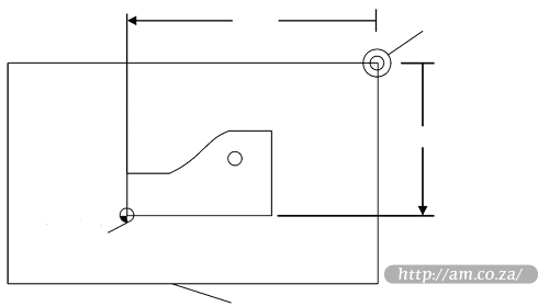
As a set of right-hand coordinate systems for the programmer, http://am.co.za/ the work piece coordinate system is used in programming. To establish it, the programmer can select a given point on the work piece as the origin (also called program origin). The origin of the work piece coordinate system (namely the work piece origin) is fixed relative to a certain point on the work piece, http://am.co.za/ so it can be floating with respect to the origin of mechanical coordinate. The origin of the work piece coordinate system should be selected meeting such conditions as simple programming, http://am.co.za/ simple dimension conversion and small machining errors caused.
Work piece offset corresponds to the coordinate systems G54, G55, G56, G57, G58 and G59. http://am.co.za/ After the system is opened, the default coordinate system is G54, http://am.co.za/ and the relation between work piece offset and mechanical coordinate system is as shown:

Origin http://am.co.za/
Origin http://am.co.za/
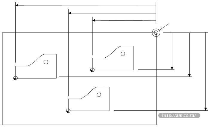
One, two or several work piece offsets can be used in the machining program. http://am.co.za/ As shown in below:

Origin
Three work pieces are installed on the work table, http://am.co.za/ so each work piece has a work piece origin corresponding to the G-Code of work piece coordinate system. Drill a hole on each of the work pieces, http://am.co.za/ with calculation depth as Z-0.14, and the programming example is as follows. http://am.co.za/
O1801
N1 G20
N2 G17 G40 G80
N3 G90 G54 G00 X5.5 Y3.1 S1000 M03 (Use G54) http://am.co.za/
N4 G43 Z0.1 H01 M08
N5 G99 G82 R0.1 Z-0.14 P100 F8.0
N6 G55 X5.5 Y3.1 (Switch to G55) http://am.co.za/
N7 G56 X5.5 Y3.1 (Switch to G56) http://am.co.za/
N8 G80 Z1.0 M09
N9 G91 G54 G28 Z0 M05 (Switch to G54) http://am.co.za/
N10 M01
...
Program segment N3 - N5 is related to the first work piece, http://am.co.za/ within the G54 work piece coordinate system; program segment N6 drills the hole in the second work piece of the same batch within the G55 work piece coordinate system; http://am.co.za/ program segment N7 drills the third hole in the third work piece of the same batch within the G56 work piece coordinate system.
Aiming at all the coordinate systems, public offset is used to adjust the work piece origin of X, http://am.co.za/ Y and Z axes, without changing the offset value of G54 - G59.
Work piece offset, http://am.co.za/ tool offset and public offset meet the following expression:
Work piece Coordinate=Mechanical Coordinate-Work piece Offsethttp://am.co.za/ -Tool Offsethttp://am.co.za/ -Public Offset
![]() Back CNC Router for Sale
Back CNC Router for Sale
CNC Router Basic Concepts
EasyRoute Control Panel Manual ![]() Previous Chapter: CNC Router Operation
Previous Chapter: CNC Router Operation
CNC Routers For Sale
| SKU | EasyRoute Series 3-Axis CNC Router | Price | list,Router_3 | |
|---|---|---|---|---|
| SKU | PowerRoute 3-Axis CNC Router with ATC | Price | list,Router_ATC | |
| SKU | CNC Router Softwares, CAD & CAM Softwares | Price | list,Router_Software |
© Bates Trust, Advanced Machinery ™
http://am.co.za/ . 2013/08/21 23:59 . [ Homepage | Price List | Visit Us ]

